junction box diagrams Advice on wiring electrical junction box with easy to follow junction box wiring diagrams, including information on 20 and 30 amp junction boxes. Be sure which type of junction box should be . Choose Your Drill Bit Size Based on Material . Your project material also makes a difference in which size drill bit you use. What works for pine might create problems for denser .
0 · wiring junction box for lighting
1 · terminal junction box wiring guide
2 · junction box wiring identification
3 · inside a junction box
4 · how to mount junction box
5 · how do junction boxes work
6 · electrical junction box instructions
7 · 4 way junction box wiring
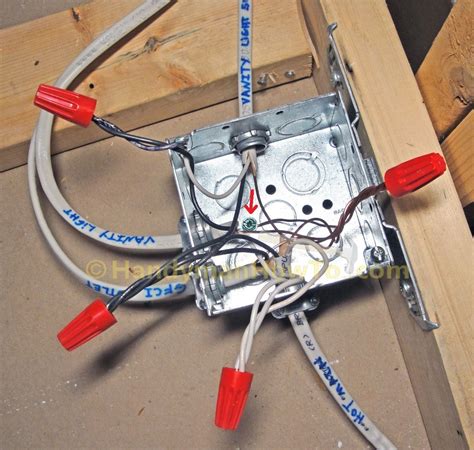
A junction box is not a special type of box but any standard electrical box used to enclose wire splices. The most commonly used box for junctions is a 4-inch square box (either metal or strong plastic), which offers ample space for making wire connections with multiple wires or .
A junction box provides a safe, code-compliant space for housing cable connections for outlets, switches, or splices. They prevent potential electrical shocks, and keep sparks from spreading to flammable surroundings.

Advice on wiring electrical junction box with easy to follow junction box wiring diagrams, including information on 20 and 30 amp junction boxes. Be sure which type of junction box should be . A junction box is a standard electrical box that contains two or more spliced electrical cables. The box must have a removable, accessible cover. Junction boxes can be .Learn how to wire an electrical junction box with a detailed wiring diagram. This article provides step-by-step instructions and illustrations to help you properly wire your junction box for safe and efficient electrical connections.Learn about junction box electrical wiring, including how to install and troubleshoot wiring connections in junction boxes for electrical circuits.
Learn how to properly wire a junction box with this wiring diagram. Follow step-by-step instructions for a safe and efficient electrical installation. By following proper installation guidelines, such as selecting the appropriate junction box size, securing cables with clamps or connectors, and ensuring the presence of a .
Learn about the wiring diagram for a junction box lighting circuit. Understand how junction boxes are used to connect and distribute electricity for lighting fixtures in your home or building.The 6 terminal junction box wiring diagram provides a visual representation of how the various wires and connections should be made within the box. It shows the layout and arrangement of .
Most junction boxes come with a wiring diagram that explains which wire should be connected to which part of the box. As long as you follow the diagram, you should be able to easily connect the wires. Once the wiring is complete, you can then connect the box to the trailer. Depending on the type of trailer, you may need to use a special .
Wiring Diagram for Junction Boxes: Simplifying Electrical Connections. A junction box is an essential component in electrical wiring systems. It acts as a central connection point for various electrical wires, allowing for the easy distribution .It is important to follow the electrical wiring diagram and color coding standards to ensure proper connections. Step 6: Test the wiring. . Choose a junction box made from a durable material that is able to withstand the environmental . The junction box wiring diagram UK is a key tool for electrical professionals as well as home owners looking to install or repair existing wiring. It provides a visual layout of the components involved in a wiring job, making it easier to .
6 Terminal Junction Box Wiring Diagram, The cables are secured to the box with cable clamps (or conduit connectors, if the circuit includes conduit ), and the box must have a removable cover to create. Advice on wiring electrical junction box with easy to follow junction box wiring diagrams, including information on 20 and 30 amp junction boxesIn this ultimate guide, we will walk you through the step-by-step process of wiring an electrical junction box, complete with helpful diagrams to ensure a successful installation. First and foremost, it is crucial to understand the purpose and importance of an electrical junction box. These boxes are used to connect and protect electrical wires .The instrument junction box wiring diagram serves as a useful reference for technicians and engineers during installation, troubleshooting, and maintenance activities. It allows them to quickly identify the various components, their connections, and any potential issues or faults. By following the wiring diagram, technicians can ensure that the . This article details the location of the fuse and relay boxes, with their diagrams and descriptions, suitable for all 1997-2000 Dakota models (ST, R/T, Sport, SLT, SXT, SXT+) and also for Regular Cab, Extended Cab, Quad Cab and Club Cab. . Interior fuse box (junction block) is located on the left side of the instrument panel and is protected .
A Junction box schedule is a document that lists all of the instrument junction boxes. Information like the JB position, tag number, size, make, IP rating, cable specifications, gland details, termination specifications, and earthing details are all mentioned in this document. illustrations on how to wire switches and lights using junction boxFuse box diagrams presented on our website will help you to identify the right type for a particular electrical device installed in your vehicle. Use our website search to find the fuse and relay schemes (layouts) designed for your vehicle and see the fuse block’s location. Likewise, you can select the car make and model listed below or from .CONNECTION DIAGRAMS DIN / ISO * The three ground wires may not be electrically connected trailer-laterally. Title: connection diagrams.indd Created Date: 3/15/2012 4:23:46 PM .
When it comes to electrical wiring, one important component that plays a crucial role in ensuring safety and durability is the junction box. A junction box is a container used to house electrical connections, protecting them from damage and preventing the risk of electrical fires.A Field Junction Box is used to concentrate the signals into multi-conductor homerun cables or main cables. The homerun cables then terminate in a remote or marshalling cabinet where the signals are marshalled (reorganized) as .
If a junction box will not be used, you can cut the ring terminals off and use heat shrink butt connectors to join the new 7-way harness directly to the trailer’s existing wires. Again, follow the wiring diagram to ensure proper wire . Thanks to their ease of use and convenience, junction box wiring diagrams PDFs are now the preferred choice for many electricians and DIYers alike. Whether you’re a professional or just getting started with an electrical .A junction box diagram, or as sometimes called - a JB drawing, as a minimum will show: - the junction box number, - field instruments and their cable number, - the terminal numbers to which the instrument is terminated, - the multicore number and its destination, - which multicore pair each field instrument is connected to.Pedalboard Interface (AKA Junction Box or Patchbay) based around an amplifier with an FX Loop. XOXO, ~ Uncle Mason, The Rig Doctor . . Use the wiring diagram below, following the color coded connections that you'll solder to the corresponding 1/4" jacks. Print the larger wiring diagram below if needed:

Radyr Junction: Box diagram (for 1961, 1984 and 1987) as well as the mechanical locking table, the lever leads and the dog chart for 1987. S1495: Pengam Junction: Dog chart for 1951. S1825: Resolven East: Box diagram for 1950 as well as the mechanical locking table .
wiring junction box for lighting
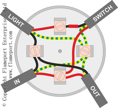
An alternative method, this uses the same wiring principles as the looped ceiling roses, but here the connections are made in junction boxes rather than the ceiling rose. The junction box effectively replaces the ceiling rose. As with the ceiling rose, the IN cable supplies power from the consumer unit or previous junction box, and the OUT . Most of the time I get lucky by typing out in google gmupfitter wiring diagram then type the make model and year of the truck . Do you have the pinout diagram for the junction box ? I looked at GMOutfitter but could not find pinout yet for junction box and blue plug. Likely have issue with left turn signal power wire from blue plug, need to .
Light switch wiring diagram with power feed in the ceiling and an electrical outlet connected. The Light switch wiring diagram above shows electrical power entering the ceiling light electrical box and then continuing to a wall switch using a three-conductor cable. A 2-conductor cable was used from the wall switch to power two electrical .The VAV box wiring diagram provides a visual representation of the electrical connections and components involved in the operation of the VAV box. It typically includes information on the power supply, control signals, and communication lines. . Junction boxes: These are used for housing electrical connections and ensuring they are protected. That's why it is important to understand the basics of Ifor Williams trailer junction box wiring diagrams. A junction box is a central point where two or more electrical wires meet and connect. In the case of Ifor Williams trailers, the junction box is typically located on the inside wall or bottom of the trailer.
For every junction boxes, it is recommended to have a width & height in the range of 100-500 mm and depth as per the manufacturer’s recommendation. Terminal Block Back Plate. The terminal blocks of a junction box are usually installed inside the junction box in .
Fuse box diagrams (location and assignment of electrical fuses and relays) Ford Transit / Tourneo (2007, 2008, 2009, 2010, 2011, 2012, 2013, 2014).

metal security file box

Use a PVC male adapter and maybe a small piece of PVC conduit that will connect to the back of the box and enter into the wall towards the interior of your house. Also be sure to seal around the hole that you drill using duct seal. Use a hole saw is slightly bigger than the PVC male adapter.
junction box diagrams|how do junction boxes work