contactor connected to electrical box A contactor wiring diagram is a visual representation of the electrical connections and components of a contactor. It provides a detailed outline of how the contactor is wired and how it operates in an electrical circuit. H. Weiss Machinery is a full service sheet metal machinery and supply distribution center.We take pride in supplying sheet metal fabricators with the highest quality new & used machinery, replacement parts, hand tools, consumables, machinery repairs and complementary services.
0 · what is power contactor
1 · what is a motor contactor
2 · what is a contactor coil
3 · parts of a contactor
4 · line contactor
5 · contactor panel
6 · contactor lc1d150
7 · ac3 contactor
【All-Purpose Propane Torch 】Weed Burning Roof Asphalt Melting, Soldering, Snow Melting, burning brush piles, Paint Removal, wood treatment, Wood Fire Starting, and Searing. It's ideal for commercial, farms and gardens.
Use these tips to learn how to wire a contactor. Look over the contactor manufacturer information to identify the input and output pins. .A contactor wiring diagram is a visual representation of the electrical connections and components of a contactor. It provides a detailed outline of how the contactor is wired and how it operates in an electrical circuit.Follow the recommended wire size for the motor and contactor to ensure that the electrical load is properly handled. Choose a contactor that has the appropriate voltage and current ratings for .This post reviews electrical contactor wiring, how electric contactors work, and introduces standard electrical contactor wiring diagram instructions to help you when selecting and installing Contact Kits and Motor Control Parts.
A contactor wiring diagram is a schematic representation of the electrical connections and arrangement of a contactor in an electrical circuit. A contactor is a device that is used to control the flow of electrical current through a circuit. How to Wire Motor Starters and Contactors This article investigates the basic components and wiring conventions for common three-phase motor starter configurations, including direct online, reversing, and star .
Learn what a contactor is, how it works, how to wire a contactor, and the difference between a contactor and a relay. Contactors are vital electrical components that function primarily as powerfully controlled switches within electrical circuits. These devices are adept at managing high-power .It works by creating a connection between two electrical contacts that allows current to flow through when the contactor is energized. The contactor consists of a coil, contacts, an electromagnet, and an enclosure.Overall, understanding the wiring diagram for a 220v contactor is crucial for proper installation and operation. It ensures that the contactor operates safely and efficiently, allowing for smooth and .
Use these tips to learn how to wire a contactor. Look over the contactor manufacturer information to identify the input and output pins. Determine if the contactor has an auxiliary output contact. Strip the wires. Run all input and output wires to .A contactor wiring diagram is a visual representation of the electrical connections and components of a contactor. It provides a detailed outline of how the contactor is wired and how it operates in an electrical circuit.Follow the recommended wire size for the motor and contactor to ensure that the electrical load is properly handled. Choose a contactor that has the appropriate voltage and current ratings for the motor to prevent overheating and damage. Use a wiring diagram specific to the motor and contactor setup to ensure proper connections and wiring .This post reviews electrical contactor wiring, how electric contactors work, and introduces standard electrical contactor wiring diagram instructions to help you when selecting and installing Contact Kits and Motor Control Parts.
A contactor wiring diagram is a schematic representation of the electrical connections and arrangement of a contactor in an electrical circuit. A contactor is a device that is used to control the flow of electrical current through a circuit.
what is power contactor

what is a motor contactor
How to Wire Motor Starters and Contactors This article investigates the basic components and wiring conventions for common three-phase motor starter configurations, including direct online, reversing, and star-delta. Learn what a contactor is, how it works, how to wire a contactor, and the difference between a contactor and a relay.

Contactors are vital electrical components that function primarily as powerfully controlled switches within electrical circuits. These devices are adept at managing high-power loads, making them indispensable in industrial and commercial settings.
It works by creating a connection between two electrical contacts that allows current to flow through when the contactor is energized. The contactor consists of a coil, contacts, an electromagnet, and an enclosure.Overall, understanding the wiring diagram for a 220v contactor is crucial for proper installation and operation. It ensures that the contactor operates safely and efficiently, allowing for smooth and reliable operation of the connected electrical devices. Use these tips to learn how to wire a contactor. Look over the contactor manufacturer information to identify the input and output pins. Determine if the contactor has an auxiliary output contact. Strip the wires. Run all input and output wires to .
A contactor wiring diagram is a visual representation of the electrical connections and components of a contactor. It provides a detailed outline of how the contactor is wired and how it operates in an electrical circuit.Follow the recommended wire size for the motor and contactor to ensure that the electrical load is properly handled. Choose a contactor that has the appropriate voltage and current ratings for the motor to prevent overheating and damage. Use a wiring diagram specific to the motor and contactor setup to ensure proper connections and wiring .This post reviews electrical contactor wiring, how electric contactors work, and introduces standard electrical contactor wiring diagram instructions to help you when selecting and installing Contact Kits and Motor Control Parts.
A contactor wiring diagram is a schematic representation of the electrical connections and arrangement of a contactor in an electrical circuit. A contactor is a device that is used to control the flow of electrical current through a circuit. How to Wire Motor Starters and Contactors This article investigates the basic components and wiring conventions for common three-phase motor starter configurations, including direct online, reversing, and star-delta. Learn what a contactor is, how it works, how to wire a contactor, and the difference between a contactor and a relay.
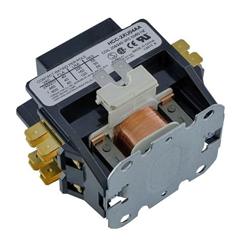
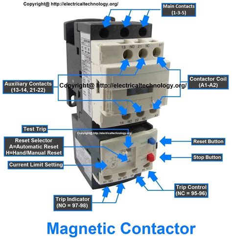
Contactors are vital electrical components that function primarily as powerfully controlled switches within electrical circuits. These devices are adept at managing high-power loads, making them indispensable in industrial and commercial settings.It works by creating a connection between two electrical contacts that allows current to flow through when the contactor is energized. The contactor consists of a coil, contacts, an electromagnet, and an enclosure.

what is a contactor coil

bulletproof metal sheets
There is one commonality between stick or torch welding thick sections and welding sheetmetal. In both of them, a serviceable weld often, but not always, has a good-looking, even, penetrated, and uniform appearance.
contactor connected to electrical box|contactor panel