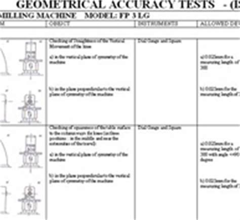
cnc machine geometrical test chart In this blog post, we will explore the importance of test charts in optimizing the accuracy and performance of CNC machines. Test charts are essential tools used by manufacturers, . The main service panel is the distribution center that splits the main electrical service into individual branch circuits that run through your home to power the lights, outlets, .
0 · Test conditions for machining centres ? Part 6: Accuracy of
1 · Mastering CNC Machine Geometrical Test Charts: A
2 · ISO 230
3 · INTERNATIONAL ISO STANDARD 230
4 · Geometric error measuring, modeling, and compensation for
5 · Geometric Accuracy, Volumetric Accuracy and
6 · Geometric Accuracy of Large Machine Tools
7 · Checking the Geometric Accuracy of a Machine Tool for
8 · (PDF) Studies and Practice of Geometrical Test
Look at a gauge thickness chart and order some small pieces to feel. Steel studs for commercial buildings are usually 16-18 gauge. 16 gauge is 1/16th of an inch thick. If aluminum, I would probably use 10-14 gauge, steel maybe 14-18 gauge.Common gauges range from 14 gauge-24 gauge for galvanized steel and 8 gauge-22 gauge for stainless steel. The higher the gauge, the thinner the metal. For example, a 14 gauge sheet of stainless steel is thicker than a 20 gauge .
In this blog post, we will explore the importance of test charts in optimizing the accuracy and performance of CNC machines. Test charts are essential tools used by manufacturers, . Geometric accuracy describes the geometric structure of a machine tool from which the properties of functional parts affecting its working accuracy can be evaluated. It also describes the production quality of the .
ISO 230 consists of the following parts, under the general title Test code for machine tools: — Part 1: Geometric accuracy of machines operating under no-load or quasi-static conditions — Part .Part 1: Geometric tests for machines with horizontal spindle (horizontal Z-axis)?
This chapter presents geometric accuracy tests, instrumentation and examples of selected procedures to increase the geometric accuracy of CNC machine tools.Part 1: Geometric accuracy of machines operating under no-load or quasi-static conditions. For the purposes of this document, the following terms and definitions apply.
This paper presents the control parameters and results of selected geometric accuracy tests for a refurbished vertical spin-dle milling machine. The tests were performed according to ISO . Specific methods for geometric errors measurement and identification are discussed. The methods for geometric error modeling and sensitivity analysis are reviewed. .
The presented study captures and presents changes in the ambient conditions of a large CNC machine tool, including its efects on the geometric accuracy of the machine. The first part of .
This paper puts forth some basic Geometrical Tests performed on SB CNC 60 Lathe Machine Tool unit, identifying major deviations measurements and reconditioning the machine parts.In this blog post, we will explore the importance of test charts in optimizing the accuracy and performance of CNC machines. Test charts are essential tools used by manufacturers, engineers, and operators to ensure precise and consistent machining results. Geometric accuracy describes the geometric structure of a machine tool from which the properties of functional parts affecting its working accuracy can be evaluated. It also describes the production quality of the machine and its assembly in an unloaded state.ISO 230 consists of the following parts, under the general title Test code for machine tools: — Part 1: Geometric accuracy of machines operating under no-load or quasi-static conditions — Part 2: Determination of accuracy and repeatability of positioning of numerically controlled axes
Part 1: Geometric tests for machines with horizontal spindle (horizontal Z-axis)?

metal sheet for balcony
Test conditions for machining centres ? Part 6: Accuracy of

This chapter presents geometric accuracy tests, instrumentation and examples of selected procedures to increase the geometric accuracy of CNC machine tools.Part 1: Geometric accuracy of machines operating under no-load or quasi-static conditions. For the purposes of this document, the following terms and definitions apply.
For this milling machine, we selected eight geometrical accuracy tests from the ISO 10791-2 standard for a machine with a vertical spindle, and two accuracy tests for horizontal milling machines. For each geometric accuracy test, we performed at least as many measurements as were stipulated in the standard. Specific methods for geometric errors measurement and identification are discussed. The methods for geometric error modeling and sensitivity analysis are reviewed. The advancements of geometric error compensation techniques and .The presented study captures and presents changes in the ambient conditions of a large CNC machine tool, including its efects on the geometric accuracy of the machine. The first part of the article describes the geometric errors of the assessed machine.
This paper puts forth some basic Geometrical Tests performed on SB CNC 60 Lathe Machine Tool unit, identifying major deviations measurements and reconditioning the machine parts.
In this blog post, we will explore the importance of test charts in optimizing the accuracy and performance of CNC machines. Test charts are essential tools used by manufacturers, engineers, and operators to ensure precise and consistent machining results. Geometric accuracy describes the geometric structure of a machine tool from which the properties of functional parts affecting its working accuracy can be evaluated. It also describes the production quality of the machine and its assembly in an unloaded state.ISO 230 consists of the following parts, under the general title Test code for machine tools: — Part 1: Geometric accuracy of machines operating under no-load or quasi-static conditions — Part 2: Determination of accuracy and repeatability of positioning of numerically controlled axes
Part 1: Geometric tests for machines with horizontal spindle (horizontal Z-axis)? This chapter presents geometric accuracy tests, instrumentation and examples of selected procedures to increase the geometric accuracy of CNC machine tools.
Part 1: Geometric accuracy of machines operating under no-load or quasi-static conditions. For the purposes of this document, the following terms and definitions apply.
For this milling machine, we selected eight geometrical accuracy tests from the ISO 10791-2 standard for a machine with a vertical spindle, and two accuracy tests for horizontal milling machines. For each geometric accuracy test, we performed at least as many measurements as were stipulated in the standard. Specific methods for geometric errors measurement and identification are discussed. The methods for geometric error modeling and sensitivity analysis are reviewed. The advancements of geometric error compensation techniques and .
Mastering CNC Machine Geometrical Test Charts: A
The presented study captures and presents changes in the ambient conditions of a large CNC machine tool, including its efects on the geometric accuracy of the machine. The first part of the article describes the geometric errors of the assessed machine.
metal sheet door

How does a distribution amplifier in a fiber node receive the downstream radio frequency (RF) signals? Through a coaxial cable that is connected to the downstream optical receiver. See an .
cnc machine geometrical test chart|Geometric Accuracy of Large Machine Tools